This guide is written for pipeline technicians and specialist contractors who need a clear, sequenced reference for the complete stopple installation process — from hot tap through completion plug seating. It also covers what to check before you start, the most common failure points in the field, and how to confirm the installation is complete before restoring full line pressure.
Key Takeaways
- Stopple fitting installation follows four phases: hot tap, line stop insertion, maintenance work, and completion plug seating
- Every component — fitting, valve, actuator, housing, and plugging head — must be matched to pipe diameter and operating pressure before work begins
- Pipe wall thickness, weld qualifications, and fluid hazards must be verified before any welding or cutting begins
- A dropped coupon or a plugging head that doesn't fully seat are the two most common field failures — both are preventable with proper pre-job checks
- Schallert Enterprises manufactures USA-made line stop equipment for pipelines 5–84 inches in diameter, including folding heads, pivoting heads, housings, jackscrews, and completion plug setters
What Is a Pipeline Stopple Fitting?
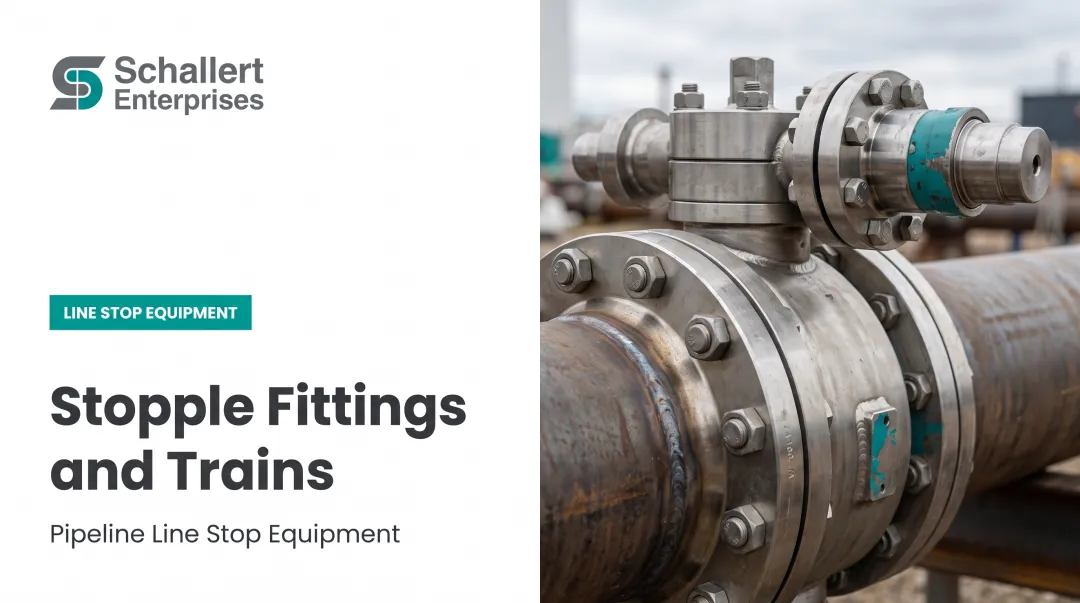
A stopple fitting is a specialized assembly used to temporarily isolate a section of a live, pressurized pipeline without shutting down flow to the rest of the system. Repairs, valve replacements, and tie-in work can proceed while the line stays in service. "Stopple" is a registered trademark of T.D. Williamson but is widely used across the industry as a generic term for line stop fittings and systems.
Core Components
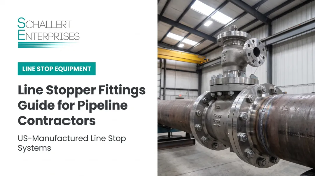
A complete stopple assembly consists of five main components:
- Full-encirclement fitting (split tee or weldolet) — welded onto the live pipe to create the branch access point
- Isolation valve (often a sandwich-style gate valve) — bolted to the fitting flange to control access to the pipe bore
- Line stop housing — connects between the valve and the actuator; houses the plugging head during travel
- Actuator (jackscrew or hydraulic) — drives the plugging head through the valve and into the pipe bore
- Plugging head (folding or pivot type) — deploys inside the pipe and seals against the bore wall to block flow
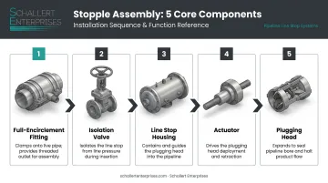
Schallert Enterprises manufactures the complete line stop equipment set — folding heads, pivoting heads, housings, jackscrews, completion plug setters, and line stop flanges — covering every stage of the process from hot tap through final completion.
Relationship to Hot Tapping
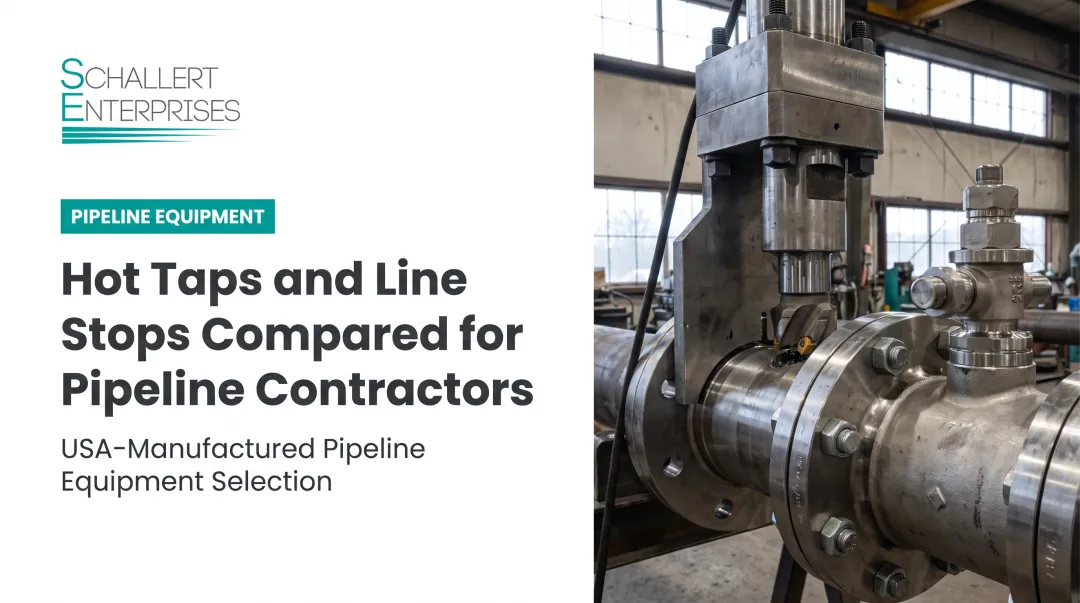
Every stopple operation begins with a hot tap, which creates the opening through which the plugging head is later inserted. Both operations use the same branch fitting but different downstream equipment — crews remove the hot tapping machine before mounting the line stop housing and actuator. A line stop cannot proceed without completing the hot tap first.
Where Stopple Fittings Are Used
- Municipal water main valve replacement
- Water distribution system repairs requiring flow continuity
- Oil and gas pipeline tie-ins and modifications
- Gas distribution maintenance work
- Industrial process piping changes where shutdown is too costly
Size and Pressure Availability
Size ranges vary by manufacturer and product line. Rangeline's line stopping service covers 2-inch to 84-inch pipe. Schallert's folding head line stop machines cover 5 to 84 inches in diameter. On the pressure side, TDW's STOPPLE plugging heads are rated to 1,480 psi, while folding head systems typically operate at lower working pressures — Schallert's folding head sealing elements are rated to 150 psi, with structural head ratings reaching 250 psi on most mid-to-large sizes.
Complete Installation Guide for Pipeline Stopple Fittings
Stopple fitting installation follows a fixed four-phase sequence: hot tap, line stop insertion, maintenance work, completion. Skipping steps or reversing the sequence on a pressurized system creates serious risk. Follow the process in order.
Prerequisites and Safety Considerations
Before any welding or cutting begins, verify each of the following:
Pipe condition checks:
- Confirm pipe wall thickness using ultrasonic gauges. API RP 2201 recommends a minimum base metal thickness of 3/16 inch for most hot tapping applications, with the actual minimum based on strength requirements plus a burn-through safety factor
- Check for laminations, hydrogen attack, or stress corrosion cracking in the pipe wall — these conditions are disqualifying without engineering review
- Verify that pipe material is compatible with welding under pressure
Component compatibility:
- The fitting must be rated for the pipeline's operating pressure and diameter
- The valve bore must be large enough for the plugging head to pass through fully
- The actuator and housing must match the valve and fitting configuration
Non-negotiables — do not proceed if:
- Wall thickness is marginal for welding under pressure
- Welder and operator qualifications are not current per applicable codes
- Fluid content (sour gas, hazardous liquids) has not been assessed and mitigated
- The crew lacks direct experience with pressurized pipeline work
Per 49 CFR 192.627, hot taps on gas pipelines must be performed by a crew qualified for the work. OSHA 29 CFR 1910.252 also requires that welding on equipment containing flammable substances follow API hot tapping guidance.
Tools and Equipment Required
Permanent installation components:
- Full-encirclement split tee fitting, sized for the pipe diameter and pressure class
- New studs, nuts, and gaskets for the completion flange blind
Temporary process equipment:
- Isolation valve (sandwich-style gate valve)
- Hot tapping machine with appropriately sized cutter and pilot drill
- Line stop housing and actuator (jackscrew or hydraulic)
- Plugging head — folding or pivot type, matched to pipe diameter
- Completion plug setter and completion flange (matched set)
- Bypass piping, if downstream flow must be maintained during isolation
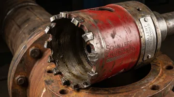
The hot tap cutter must create an opening large enough for the plugging head to pass through after the tap is complete — cutter selection directly determines whether the plugging head can deploy. Schallert manufactures carbide-tipped, HSS-tipped, and diamond segment cutters for this purpose, including an 11.875-inch cutter available in all three styles, sized to allow a compatible folding head to pass through. All cutters feature a deep tooth profile to prevent material buildup during the cut.
How to Install a Stopple Fitting (Step-by-Step)
Step 1 — Fit and weld the branch fitting
Install the full-encirclement split tee onto the live pipeline. Once welded, pressure test the fitting-to-pipe weld before proceeding. Do not move forward without confirming weld integrity.
Step 2 — Mount the valve and hot tap machine
Bolt the isolation valve onto the fitting flange using new gaskets. Mount the hot tapping machine onto the valve. Confirm alignment and measurements before starting the cut.
Run the hot tap in one continuous operation until the cutter passes fully through the pipe wall and the coupon is retained on the pilot drill u-wires. Then:
- Retract the cutter fully (the boring bar must clear the valve gate before closing)
- Close the valve
- Remove the hot tap machine
- Confirm the coupon is present in the cutter assembly before proceeding
Step 3 — Deploy the bypass (if required)
Where downstream customers or processes require continuous flow during isolation, install bypass piping connected to valve housings on both sides of the work zone before inserting the line stop head.
Step 4 — Install the actuator and insert the plugging head
Bolt the line stop housing and actuator onto the valve using new gaskets. Operate the actuator to advance the plugging head through the open valve and into the pipe bore.
Confirm the head has pivoted or folded fully into the sealing position against the flow direction. Then relieve pressure from the isolated section to verify isolation is complete.
Where pressurized or hazardous gas is present, use controlled venting equipment. Do not open the isolated section to atmosphere without pressure verification first.
Step 5 — Complete maintenance work and set the completion plug
With the section isolated, perform the required repair, valve replacement, or modification. Once work is done:
- Equalize pressure across the plugging head
- Retract the head behind the valve gate using the actuator
- Remove the actuator and housing
- Insert the completion plug through the valve into the line stop fitting flange using the completion plug setter
- Lock the plug in place with lock ring segments
- Confirm the seal (o-ring or metal-to-metal) is fully seated
- Bleed pressure above the plug
- Remove the valve
- Install the completion flange blind with new studs, nuts, and gaskets
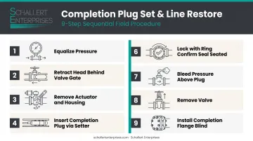
Schallert's completion plug setters (models PS0410, PS0616, and PS1836) cover plug sizes from 4 to 36 inches and are rated to 500 psi. They are designed as a matched system with Schallert's line stop flanges — the plugs and setter tools are engineered to work together, though Schallert can adapt the flanges to alternative plug-setting methods on request.
Post-Installation Checks and Validation
Before restoring full line pressure:
- Visual inspection — Check all welds, flange connections, and the completion flange blind for signs of leakage, misalignment, or seal failure
- Pressure hold test — Confirm the completion plug is holding and no pressure is escaping through the fitting; verify the plug cannot shift under operating pressure
- Coupon accountability — Confirm the coupon was retained and is physically accounted for
A correctly completed installation shows zero pressure loss at the completion flange, no visible leakage at fitting welds, and a locked, verified completion plug. Skipping this validation step is one of the most common causes of failures that only become apparent after full line pressure is restored.
Common Installation Problems and Fixes
Most field failures occur during the hot tap phase or at completion plug setting. Knowing the symptoms early lets crews correct problems before they escalate.
Coupon Drop During Hot Tapping
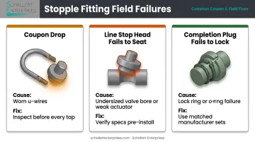
The cut coupon is not retained and drops into the live pipeline bore. This typically traces back to worn or incorrectly configured u-wires on the pilot drill, or the cutter advancing too fast before wire engagement is confirmed.
To prevent this:
- Inspect u-wires before every hot tap and replace if worn
- After retracting the cutter, confirm the coupon is present before closing the valve
- Per API RP 2201, if a coupon is lost, do not attempt retrieval using the hot tapping machine
Line Stop Head Fails to Fully Seat
The plugging head does not fully pivot or fold into the sealing position, leaving isolation partial or failed. Common causes include a valve bore too small to allow the head to clear, an underpowered actuator for the pipe diameter, or a housing too short to accommodate full head travel.
Before installation, verify that the valve bore, actuator, and housing are all correctly specified for the pipe diameter. If the head stalls mid-travel, stop and investigate the obstruction rather than forcing the actuator.
Completion Plug Fails to Lock or Seal
Pressure bleeds past the completion plug after the valve is removed, or the plug cannot be secured. This points to lock ring segments not fully engaged, an o-ring damaged during insertion, or a mismatched completion plug and flange combination.
Steps to resolve:
- Use only manufacturer-specified completion plug and flange sets
- Inspect o-rings before insertion and replace any that show damage
- Confirm lock ring engagement visually or by specified torque before bleeding pressure above the plug
Pro Tips for Installing Stopple Fittings Effectively
These field-tested practices help crews avoid the most common failure points during stopple fitting installations.
- Install in pairs. Place one stopple fitting on each side of the work zone when isolating a section for repair — a single-side stop does not provide full isolation.
- Never reuse gaskets. Use fresh gaskets at every stage, especially at the final completion flange blind, where that seal determines long-term fitting integrity.
- Document pipe wall thickness measurements, pressure test results, coupon retention confirmation, and completion plug lock verification. This record provides regulatory traceability under PHMSA Part 192 requirements.
- Confirm cutter-to-plugging-head sizing before the job starts. The hot tap opening must be large enough for the plugging head to enter the bore cleanly — not a detail to discover after the tap is complete.
- For 36-inch-and-above pipelines or elevated operating pressures, bring in crews with proven large-diameter experience. A team qualified on 12-inch work is not necessarily ready for 60-inch line stops.
Conclusion
Every phase of a stopple fitting installation — from the quality of the fitting weld to how cleanly the completion plug seats — has a direct bearing on whether a live pipeline remains safe, functional, and leak-free. Shortcuts at any stage create compounding risk on a pressurized system.
Before restoring line pressure, confirm:
- Fitting weld passes visual and pressure inspection
- Completion plug is fully seated and torqued to spec
- All vent and test ports show no active leakage
- Post-installation pressure test holds at operating pressure
Plan the job thoroughly, use equipment that is rated and matched for the application, and perform full post-installation validation before restoring line pressure. For high-stakes applications, bring in experienced pipeline technicians. A fitting failure on a live pressurized line puts personnel, infrastructure, and service continuity at immediate risk — consequences that no amount of corrective maintenance can fully undo.
Frequently Asked Questions
What is a stopple fitting?
A stopple fitting is a specialized assembly used to temporarily isolate a section of a live, pressurized pipeline without shutting down flow. It enables repair, valve replacement, or modification work while the system remains in service. "Stopple" is a T.D. Williamson registered trademark but is widely used as a generic industry term.
What size are stopple fittings?
Sizes span a wide range depending on the manufacturer. Schallert Enterprises' folding head line stop machines cover 5 to 84 inches in diameter. Selection depends on pipeline diameter and the clearance required for the plugging head to enter the bore.
What is the difference between hot tapping and line stopping?
Hot tapping creates a pressurized branch connection on a live line, used for tie-ins or as the first step in a line stop operation. Line stopping goes further: a plugging head is inserted through that hot tap opening to fully block flow in the pipe, isolating a section for maintenance or repair.
Can a stopple fitting be installed on a live pressurized pipeline?
Yes. The hot tap and line stop sequence is specifically designed for in-service, pressurized pipelines. Installation does not require shutting down the line or interrupting flow to the rest of the system.
What is a completion plug and when is it used?
A completion plug is inserted into the stopple fitting flange after line stop work is finished. It creates a permanent pressure seal that allows the temporary valve and all line stop equipment to be removed, leaving only the fitting on the pipe.
What materials are stopple fittings made from?
Most stopple fittings are manufactured from carbon steel, with grades such as ASTM A283 Grade C and A36 commonly specified for tapping sleeves. Stainless steel options (304 and 316) are available for water and industrial fluid applications where corrosion resistance is required.